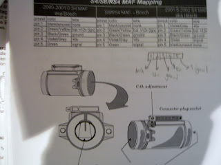
This sensor is a linier throttle position sensor, this is one of two types used. This sensor operates from a variable resitors which changes the output depending on the position of the throttle, this is an example given in the worksheet. The idle position is recognised by the lowest voltage reading through the sensor but in contrast, the maximum power signal is recognised by the highest reading at the full throttle position of the sensor travel.
The first test was to connect a power supply and test the voltage output at different throttle angles.
Throttle Angle Voltage output
0 degrees 4.8v
22.5 degrees 3.9v
30 degrees 3.5v
45 degrees 3.0v
67.5 degrees 2.1v
90 degrees 0.7v
THROTTLE POSITION SWITCH
The throttle position switch detects throttle position at idle or full throttle by using a switch which is connected or disconnected as the throttle position changes.
testing a throttle position switch is very easy, with only two steps,
Place the Ohm meter across the E and IDL pins and with the throttle shut check for continuity.
Place the Ohm meter across the E and PSW pins and check for continuity when throttle is wide open.
E and IDL
closed = infinity
open = 0.2Kohm
E and IDL
closed = 0.1Kohm
open = infinity
A throttle position switch is one of the most basic sensors with three positions, idle, cruse and wide open throttle. When the throttle is at either of these positions the ECU sets the ignition, injectors etc to the specified working conditions.
MANIFOLD ABSOLUTE PRESSURE (MAP)
In this test I had to wire up a map sensor with a 5v feed and earth and measure the return voltage from the third wire. I changed the reading my applying a vacuum to the sensor, this is the readings I got plotted on a graph.
A MAP sensor reads the pressure difference. The output from the external sensor will show a rise and fall in voltage depending upon the vacuum seen. With the engine stationary or the throttle wide open, zero vacuum will be recorded and a voltage approaching 5v will be seen. As a vacuum is applied the voltage will reduce.
AIR FLOW/MASS SENSORS (MAF)
When I first powered up the sensor without any air passing over it I got a reading of 1.12v coming out of it, when we started blowing over the sensor the voltage changed between 2.13v and 3v. As the air passes through the sensor, as the engine revs up and the airflow increases as the vehicle accelerates the airflow increases and cools the thermistor and lowers it resistance, when the airflow decreases the thermistor heats up and the resistance increases.
VANE or FLAP AIR FLOW SENSOR/METER (AFM)
KNOCK SENSOR
As the knock sensor detects and knock in the engine this creates a small vibration inside the sensor. The sensor contains Peizo crystals which create a small voltage when a vibration occurs.
SPEED or POSITION SENSORS
Then I had to measure the air gap on a magnetic distributor.
HALL EFFECT SENSORS
In this test I had to wire up a distributor as shown in the wiring diagram, Connect an oscilloscope then spin the distributor and observe the waveform.
INJECTOR TESTING
Injectors from systems that use dropping resistors in the power feed to the injector can be identified from those that do not by their resistance value.
Common values:
With resistor - 1.5 , 3.0 ohms
Without resistor - 14.0, 17.0 ohms
Then I had to wire up the injectors to listen to them to see if they are working.

One other engine problem that could give the same result as an injector not firing could be no pressure in the fuel rail.
Testing injectors
After testing all of the injectors I found that two of the injectors had flow pattern problems, This could probably be fixed by cleaning them. All of the injectors had the same flow rate over the time I tested them, The two with the uneven spray pattern had an offset pattern.
IGNITION COILS
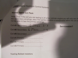
My calculated values nearly equaled the same voltage drop, the reason for the slight difference would be from the multimeter and old components.


